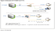
NGA architectures based almost exclusively on fibre are known as FTTH/B/P: Fibre To The Home / Fibre To The Building / Fibre to the Premises and differ from FTTC: Fibre to Curb / Fibre to the Cabinet (sometimes also referred to as FTTN) and may be characterized according to the siting of the fibre termination point with respect to the end-user (see Figure 10).
Figure 10 - Structure of FTTH/B/P and FTTC 1
Given the investments currently underway in Portugal and in various countries, as well as the technological options which, in the near future, appear to give more guarantees in terms of transmission speed evolution, this approach will focus primarily on FTTH architecture. It is noted that FTTC/N architecture with respect to VDSL is addressed in 3.3 .
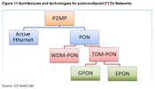
FTTH/B/P networks (including FTTH) can be deployed using point-multipoint or point-to-point architectures. The point-multipoint architecture is subdivided, in terms of potential technologies, into Active Ethernet and PON and the latter into TDM/PON and WDM-PON (see Figure 11).
Figure 11 - Architectures and technologies for point-multipoint FTTH Networks
Point-to-point
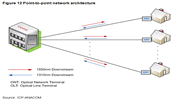
Point-to-point architecture is the simplest from a conceptual standpoint. With this architecture, a fibre is installed directly between the customer's premises and the Exchange (Central Office/ODF). Briefly, point-to-point architecture comprises an OLT port/one fibre per customer, that is there a laser transmitter and a receiver dedicated to each customer. In this architecture (see Figure 12) all the bandwidth provided by the OLT (on that fibre) is assigned to a single client.
Figure 12 - Point-to-point network architecture
Point-to-point networks allow higher speeds and provision of an improved service, since there is no sharing of the physical environment and, at the same time, they are more flexible since any (substantial) change at the level of supplied speeds only implies the alteration of the active equipment at the two ends of the connection and not of the optical infrastructure. It also means greater security because the dedicated OLT is immune to any disturbance caused by other network users. On the downside, a higher initial investment is required in the installation of additional optical fibre 2, greater occupation of physical space and greater energy consumption in the Exchange because it implies an optical line terminal (laser) per client (OLT).
Point-multipoint architecture
Point-multipoint architecture (see Figure 13) has a port on the OLT for each N 3 customers and is subdivided into Active Ethernet and PON networks.
Figure 13 - Generic point-multipoint architecture
Active Ethernet
In active Ethernet architecture, the derivation point is an active node, typically an Ethernet switch, which is used to aggregate traffic from different customers (Optical Network Termination, ONT 4). Of the different point-multipoint architectures, this requires greater investment in the external network 5, since in order to aggregate fibre connected directly to end-customers, this architecture requires that the Ethernet switches 6 be installed in protected cabinets between the Exchange and the customer's premises, whereas it is necessary to take into account issues related to power supply and temperature control of the active equipment. This is a "layer 2" technology in which the function of the Active Ethernet is to relay to each end-user only the Ethernet frames destined to them, working at a logical level of analogue mode on a point-to-point network (see Figure 14).
Figure 14 - Point-multipoint network Ethernet Active
PON Architecture
Contrary to Active Ethernet, this architecture does not require any electronics (active elements) on the optical network. To share resources it uses passive optical splitters in the case of TDM-PON or a splitter/combiner in the case of WDM-PON. The ONT use the same fibre ("feed", linked to the exchange) and the same port on the OLT, making the use of multiple access techniques necessary to avoid collisions in the communication between the exchange and end-user. As such, PON networks are divided into TDM-PON 7 and WDM-PON 8 (see Figure 11), with the first operating using time (i.e. two ONT may not transmit at the same time) and the latter operating using wavelength (i.e., each ONT transmits on a different wavelength).
TDM-PON
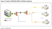
As mentioned above, on TDM-PON (EPON or GPON) networks splitters are used that: (a) downstream, split the optical signal that reaches the OLT sending it to each ONT and (b) upstream, combine each optical signal with the same wavelength emitted by each ONT into a single beam (see Figure 15). This reduces the cost of aggregation outside the exchange, since the cost of the optical splitter is low and it requires no power supply and little or no maintenance.
Figure 15 - Generic TDM-PON (GPON or EPON) architecture
Currently, on TDM-PON networks, the maximum concentration of subscribers per OLT is 64 (in the case of GPON) and maximum distance between active equipment is 20 km. However, at larger distances it corresponds, due to mitigations involved, to a lower concentration, typically 32. On the other hand, the maximum bandwidth provided to users can also determine a lower concentration. Currently, new solutions are under development which will allow greater distances with the same or even higher concentration of subscribers (per OLT and/or splitter).
The most used variants of TDM-PON are GPON 9 (ITU-T G.984.1) and EPON 10 (IEEE 802.3ah). The first operates at an aggregate line speed of 2.5/1.2 Gbps and the second at a symmetrical speed of 1.25/1.25 Gbps. EPON networks 11 were the first to be developed and have a higher prevalence in Japan and South Korea, countries which were first to develop optical fibre networks reaching consumers. GPON 12 networks, which were developed later, are most used in Europe and the USA.
GPON and EPON have different characteristics in relation to the aggregate line rate and efficiency of the TDMA protocol, that is the portion of total speed that can be used for payload. These two technologies also differ in terms of the power budget allowed between the OLT and the ONU, the ratios on the splitters and finally, GPON has a number of advantages due to greater protocol efficiency. Table 2 exemplifies the characteristics of these two architectures.
|
GPON vs. EPON |
GPON (ITU-T G984) |
EPON (IEEE 802.3ah) |
|
Downstream line speed |
2448 Mb/s |
1250 Mb/s |
|
Upstream line speed |
1244 Mb/s |
1250 Mb/s |
|
Maximum derivation |
1:64, 1:32 (typical) |
1:32, 1:16 (typical) |
|
Maximum range |
20 Km |
20 Km |
|
Average Efficiency 13 (ε) |
≈ 93% |
≈ 65-70% |
|
Traffic supported |
Ethernet, ATM, SDH |
Ethernet |
Source:ICP-ANACOM
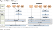
At the technological level the most obvious difference between these two network types is the architectural approach at Layer 2 level (see Figure 16). GPON (with three sub-layers in Layer 2) offers different types of traffic, such as: IP on Fast, Gigabit, or 10 Gbit Ethernet; TDM over SDH interfaces; and ATM between 155-622 Mbps. EPON, meanwhile, employs a single level 2 Layer that only uses Ethernet for transporting data, voice and video.
Figure 16 - EPON vs. GPON Layers
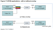
Regarding GPON (see Figure 17), data is extracted at the ONT (e.g. Ethernet and ATM) and according to ITU-T G.984.2, there is currently the possibility of using a third wavelength to introduce additional services - typically television/video, called RF Overlay 14.
Figure 17 - GPON applications - with or without overlay
Figure 17 corresponds to a complete system service with overlapping analogue video through RF Overlay using a third wavelength multiplexed with the optical signal which transports data so that the TV signal is transmitted over the same optical fibre. Figure 17 represents a fully digital system in which video, is broadcast on IPTV, using only two wavelengths.
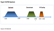
Figure 18 exemplifies how the spectrum for GPON is organized to support the two situations described above.
Figure 18 - GPON Spectrum
In the system with RF Overlay, the terminal equipment converts the optical signal into an electrical signal by separating the digital signals (data and digital video) and analogue video. The latter can be inserted into the existing coaxial network in every room of a house without additional decoding and so without need to use a set-top box 15.
The EPON variant (IEEE 802.3ah) of the passive optical network is based, as mentioned above, only on Ethernet technology, which is why it is called an EPON network (Ethernet PON). On this type of networks, the OLT is an Ethernet switch, which transmits, in the downstream direction, Ethernet frames which pass through a splitter (1:n) and are delivered to each ONT, which selects the frame meant for it from among all the frames. In the upstream direction, the problem of access/collision needs to be considered; that is, two frames simultaneously arriving at the OLT may collide. To overcome this problem the ONT are synchronized based on a TDMA scheme (Time Division Multiple Access), whereby a time slot with capacity for the transport of several Ethernet frames is allocated to each ONT.
These two architectures, GPON and EPON are evolving, and within a few years are expected to evolve into 10G-GPON 16 and 10G-EPON, with substantial improvements in performance, and allowing downstream speeds of 10 Gbps. Indeed, in September 2009, the IEEE 802.3av standard for 10G-EPON was completed, with two configurations supporting this technology: symmetric, operating at speeds of 10 Gbps, and asymmetric, with 10 Gbps downstream and 1 Gbps upstream.
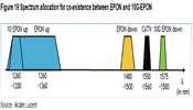
In terms of compatibility with current systems, EPON requires the management of the optical spectrum allocation, since the upstream bandwidth of 10G-EPON coincides with that of EPON (see Figure 19).
Therefore, to ensure compatibility of the two systems on the same optical fibre, the OLT will have to use wavelength division multiplexing to transmit data downstream, meaning that, upon the introduction of 10G-EPON, it will have to be replaced by one that supports all wavelengths and that is capable of differentiating upstream traffic . As such, this technology does not allow for gradual evolution, since it requires a complete alteration of the OLT, unlike with GPON.
Figure 19 - Spectrum allocation for co-existence between EPON and 10G-EPON
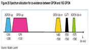
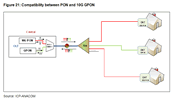
In the case of GPON, since different wavelengths are used without overlapping of bandwidth, it is simple on the reception side to separate the wavelengths for GPON and 10G GPON (see Figure 20 and Figure 21) so that the two solutions can coexist on the same network. In both situations, RF Overlay remains possible, since the video signal is transmitted with a 1555 nm wavelength 17. Upon introduction of 10G GPON, it is necessary to introduce new emission equipment and to multiplex the WDM signal through the signal of GPON in the exchange. It is noted that 10G GPON technology was standardised 18 by the ITU-T in October 2010.
Figure 20 - Spectrum allocation for co-existence between GPON and 10G GPON
Figure 21 - Compatibility between PON and 10G GPON
WDM-PON
Another PON technology, currently undergoing definition at the level of standardization 19, is WDM-PON, which supports various wavelengths and can therefore be used as a point-to-point network (one wavelength per customer) or as a point-to-multipoint network with several operators using the same network (one wavelength per operator - WDM GPON network) so that each one uses the network as if it were an actual GPON. See in this regard the following section.
WDM-PON networks are subdivided into CWDM (Coarse-WDM) 20 and DWDM (Dense-WDM) 21. It is expected that up to 40 or more customers are served by a single access fibre in the DWDM variant and 8 in the CWDM variant.
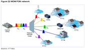
The physical topology of WDM-PON (see Figure 22) is similar to that of EPON and GPON, but there are some differences in the distribution node. In the case of DWDM, this network point consists of a splitter together with a combiner, which combines optical signals from each ONT into just one and sends it to the OLT, and a (de)multiplexer known as Arrayed WaveGuide (AWG) which forwards the different wavelengths to the different ONT. In the case of CDWM, the distribution point consists of a range of WDM equipment and CWDM (de)multiplexers.
Figure 22 - WDM PON network
This technology supports any service (Ethernet, TDM 22, ATM, etc.) in transparent from and at very high speeds per wavelength (currently up to 10 Gbps) in a logical point-to-point topology. The fact that each ONT works with wavelengths which are different from the others, thereby referred to as "coloured" ONT, makes the deployment of such networks more complex since the ONT wavelengths are different from each other, which is a disadvantage over TDM-PON, where all the ONT use the same wavelength for transmission and reception.
The solution to this problem would be to use colourless ONT, which are more complex and more costly. There is currently only one supplier known to offer this type of equipment 23. Very simply, this solution functions by transmitting all the signals as one to the distribution point. To this end, a signal is generated with very wide bandwidth on the OLT which contains all the wavelengths to be transmitted and which will be filtered by the AWG and divided into n "slices" that are sent individually to each of the n ONT.
WDM-PON technology is not yet standardized or adopted, for reasons related to the technological challenges, since the OLT requires a set of lasers (one per wavelength), which has implications in terms of costs. Apart from these aspects, the acquisition of an AWG should involve greater investment than required for the splitters used in a traditional PON (e.g. GPON).
CWDM is a low density WDM technology in terms of wavelengths. In this technique, information is grouped according to Rec. ITU-T G.694.2, into 18 channels in the 1271 nm to 1611 nm band, with a distance of 20 nm between channels.
Currently the most used frequency bands in CWDM systems are:
a) Band O (Original Band) - from 1260 nm to 1360 nm;
b) Band E (Extended Band) - from 1360 nm to 1460 nm;
c) Band C (Conventional Band) - from 1530 nm to 1570 nm.
DWDM technology (ITU-T Rec. G.694.1) differs in the number of CWDM wavelengths transmitted, which is much larger, with smaller spacing between them. Currently, these systems can use up to 80 channels (wavelengths), this number may increase further in the future. For example, to have a bandwidth of 500 Gbps, a DWDM system can support 50 wavelengths, each transmitting at 10 Gbps. However, given the complexity of the technology, and because it requires very precise lasers and filters, it is not yet in use in the access network.
Currently, the frequency bands most used in most DWDM systems are:
a) Band S (Short Band) - from 1450 nm to 1500 nm;
b) Band C (Conventional Band) - from 1530 nm to 1570 nm;
c) Band L (Long Band) - from 1570 nm to 1625 nm.
Table 3 summarises the differences between these two technologies, showing the advantages and disadvantages of each.
|
CDWM vs. DWDM |
Advantages |
Disadvantages |
|
CWDM |
|
|
|
DWDM |
|
|
Source: ICP-ANACOM
The introduction of WDM-PON networks can coexist with previously installed GPON networks allowing specific wavelength allocation to a network or, at most, to an individual customer.
1 The definition of FTTP in specialist literature is unclear, whereby it sometimes defined as FTTH is considered and otherwise as FTTB.
2 According to Alcatel-Lucent and IDATE, this figure could be around 20%, depending on conditions on the ground. If there is shortage of ducts, for example, the price of a point-to-point solution may be much higher.
3 N, theoretically, can take values between 8 and 128.
4 Equipment which terminates the fibre connection which comes from outside and where the customer's private connection begins.
5 Consisting of all cables, ducts, masts, towers, repeaters and other equipment located between a demarcation point of a switching unit and a demarcation point in another switching centre or customer premises.
6 The function of the switch, which is an active layer 2 device and commonly used in computer networks, is to relay each of the frames between the OLT and ONT.
7 Time-Division Multiplexing Passive Optical Network.
8 Wavelength-Division-Multiplexed Passive Optical Network.
9 Gigabit PON.
10 Ethernet Passive Optical Network.
11 Standardised in 2004.
12 Standardised in 2008.
13 Efficiency refers to the proportion of speed used for data transport.
14 Radio Frequency (RF) Overlay consists of the transmission over a optical fibre of the analogue video signal at a wavelength different from those used for sending data. At the client’s home, the optical signal is converted into RF and can therefore be distributed to all reception devices without requiring decoders.
15 A term that describes a device which, in its simplest form, is connected to a television set and an external signal source and converts this signal into content in a format that can be shown on that television.
16 Portugal Telecom began testing this technology in October 2010.
17 Length Unit of the International System, commonly used for measuring wavelengths of visible light, ultraviolet radiation, infrared radiation and gamma radiation. A nanometre is a subunit of meters, corresponding to 1.0 × 10 metres.
18 Recommendation G.987.3.
19 Characteristics of optical systems for terrestrial transport networkshttp://www.itu.int/ITU-T/studygroups/com15/sg15-q6.html.
20 Coarse wavelength division multiplexing.
21 Dense wavelength division multiplexing.
22 Time Division Multiplexing.
23 Ethernet over WDM PON technology overviewhttp://www.nortel.com/products/01/ethernet_access/nn123922.pdf.
24 Single-mode optical fibre.
25 Multimode fibre.
26 Erbium Doped Fibre Amplifier.

